Back Ray Casting BS Ray casting Catalan Raycasting German Ray casting Spanish Säteensuuntaus Finnish Raycasting French Sorot sinar ID 광선 투사 Korean Staru mešana Latvian/Lettish Raycasting NB

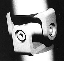
Ray casting is the methodological basis for 3D CAD/CAM solid modeling and image rendering. It is essentially the same as ray tracing for computer graphics where virtual light rays are "cast" or "traced" on their path from the focal point of a camera through each pixel in the camera sensor to determine what is visible along the ray in the 3D scene. The term "Ray Casting" was introduced by Scott Roth while at the General Motors Research Labs from 1978–1980. His paper, "Ray Casting for Modeling Solids",[1] describes modeled solid objects by combining primitive solids, such as blocks and cylinders, using the set operators union (+), intersection (&), and difference (-). The general idea of using these binary operators for solid modeling is largely due to Voelcker and Requicha's geometric modelling group at the University of Rochester.[2][3] See solid modeling for a broad overview of solid modeling methods. This figure on the right shows a U-Joint modeled from cylinders and blocks in a binary tree using Roth's ray casting system in 1979.
Before ray casting (and ray tracing), computer graphics algorithms projected surfaces or edges (e.g., lines) from the 3D world to the image plane where visibility logic had to be applied. The world-to-image plane projection is a 3D homogeneous coordinate system transformation (aka: 3D projection, affine transformation, or projective transform (Homography)). Rendering an image in that way is difficult to achieve with hidden surface/edge removal. Plus, silhouettes of curved surfaces have to be explicitly solved for whereas it is an implicit by-product of ray casting, so there is no need to explicitly solve for it whenever the view changes.
Ray casting greatly simplified image rendering of 3D objects and scenes because a line transforms to a line. So, instead of projecting curved edges and surfaces in the 3D scene to the 2D image plane, transformed lines (rays) are intersected with the objects in the scene. A homogeneous coordinate transformation is represented by 4x4 matrix. The mathematical technique is common to computer graphics and geometric modeling.[4] A transform includes rotations around the three axes, independent scaling along the axes, translations in 3D, and even skewing. Transforms are easily concatenated via matrix arithmetic. For use with a 4x4 matrix, a point is represented by [X, Y, Z, 1] and a direction vector is represented by [Dx, Dy, Dz, 0]. (The fourth term is for translation and that does not apply to direction vectors.)
- ^ Roth, Scott D. (February 1982), "Ray Casting for Modeling Solids", Computer Graphics and Image Processing, 18 (2): 109–144, doi:10.1016/0146-664X(82)90169-1
- ^ Voelker, H. B.; Requicha, A. A. G. (December 1977). "Geometric modeling of mechanical parts and processes". Computer. 10.
- ^ Requicha, A. A. G. (December 1980). "Representation for rigid solids: Theory, methods, and systems". ACM Computing Surveys. 12 (4): 437–464. doi:10.1145/356827.356833. S2CID 207568300.
- ^ .Newman, W.; Sproull, R. (December 1973). Principles of Interactive Computer Graphics. Mcgraw-Hill.